
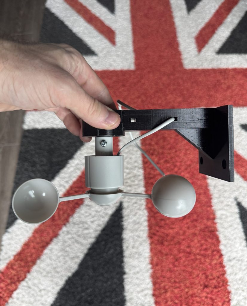
This is a full, copy-it-exactly guide to the wind sensor that now lives inside the aircon housing on the side of our condo in Manila. Total spend was about PHP 1,500 (roughly £20), the build is two wires and a 3D-printed bracket, and the reason it exists is that a weather forecast cannot tell you what the wind is doing at one particular louvre on the 30-somethingth floor of one particular building. I tried to work around that for a month with Met.no and the airport METAR feed. It did not work. So I measured it instead.
If you just want the shopping list and the config, skip to the parts and the ESPHome config. If you want the whole saga, including five attempts at printing one small plastic peg, read on.
Why on earth would you want a wind sensor inside an aircon housing?
Our condo faces west. The bedroom aircon is a split unit and the outdoor half sits in a housing cavity against the outside wall, behind a louvre, but INSIDE the condo unit. Which is the stupid standard arrangement here. In the wet season the westerlies arrive in the evening and blow straight into that louvre. When they do, the condenser’s hot exhaust gets blown back across its own intake, the unit gradually loses the ability to dump heat, and by about 3am the bedroom is creeping up half a degree an hour while the compressor works harder and harder to achieve nothing.
The night that made me do something about it was a Saturday in August. The unit lost three and a half degrees over ten hours fighting 40 km/h westerlies. My girlfriend woke up hot at ten to nine, correctly diagnosed the blowback herself, and turned the aircon off with the remote. She then went back to sleep under the ceiling fan, which is exactly what the automation I built afterwards does. She was, as usual, quicker than the software.
The obvious answer is “use the weather forecast”. I did. I had a whole storm-protection automation running off Met.no wind speed and the observed wind from Ninoy Aquino airport (RPLL), which is about 8 km away. The trouble is that the forecast is for the region and the airport is at ground level in a big open space. Neither knows anything about my louvre. The forecast would say 39 km/h while the housing had gone dead calm, so the automation would sit there with the aircon shut off for an extra hour for no reason. Or the reverse. What I actually needed was a number for “how much air is coming through this specific louvre right now”.
The plan
The plan, written down on the 10th of August before any parts arrived, was deliberately boring:
- A cheap cup anemometer. These are just a reed switch that closes once per revolution of the cups. No electronics inside, nothing to go wrong, two wires out.
- An ESP32 running ESPHome, counting the pulses and reporting a wind speed to Home Assistant over WiFi.
- Only the cups go in the housing cavity. The ESP32 lives indoors on USB power, because the cavity is hot, wet and full of compressor vibration and I did not fancy replacing a board every wet season.
- Readings would be in “cavity units”, not real wind speed. The cups sit behind a louvre that breaks some of the wind, so the number is a relative measure of how much air is getting in. That is fine. I do not care what the wind is doing in general. I care what it is doing to my condenser.
The last point matters for anyone copying this. Do not expect the number to match a weather station. Expect it to be consistent with itself, and calibrate your thresholds against a couple of weeks of real weather.
Parts and what they cost
Everything came from Shopee and AliExpress. Prices are what I paid in August 2026, delivered to Manila.
| Part | Where | Price | Notes |
|---|---|---|---|
| Misol WH-SP-WS01 cup anemometer | AliExpress | PHP 1,001 | Includes shipping. The replacement cups for the Misol / Fine Offset weather stations. Reed switch, two wires, comes with an RJ11 plug on the end. |
| ESP32 WROOM-32 dev board with 30-pin expansion shield | Shopee | PHP 384 | Sold as a set. The shield gives you a screw-free S/V/G pin row for every GPIO so no soldering is needed. USB-C on the shield for power. |
| PCT-212 lever wire connectors, pack of 5 | Shopee | PHP 51 | Bought these to join the anemometer wires. They turned out to be useless for this job. See wiring below. |
| Dupont female-to-female jumper wires, 40 pieces, 20 cm | Shopee | PHP 56 | Two of them go from the join to the shield’s pins. |
| PETG filament, screws | Already had | PHP 0 | 5 x #6 self-tappers 3.5 x 16 mm, 4 x #8 wood screws 4.2 x 32 mm. |
| Total | PHP 1,492 | About £20 or $26. |
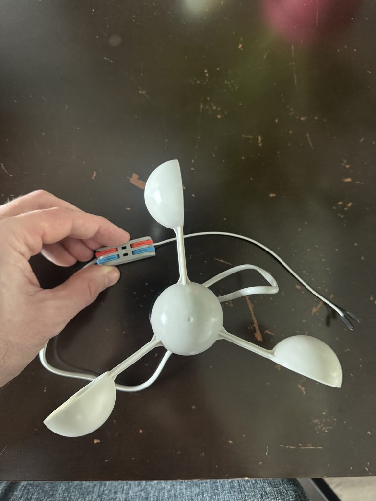
The Misol WH-SP-WS01 with its RJ11 plug already snipped off. The little red and blue lever connector is the PCT-212 that was about to waste an afternoon.
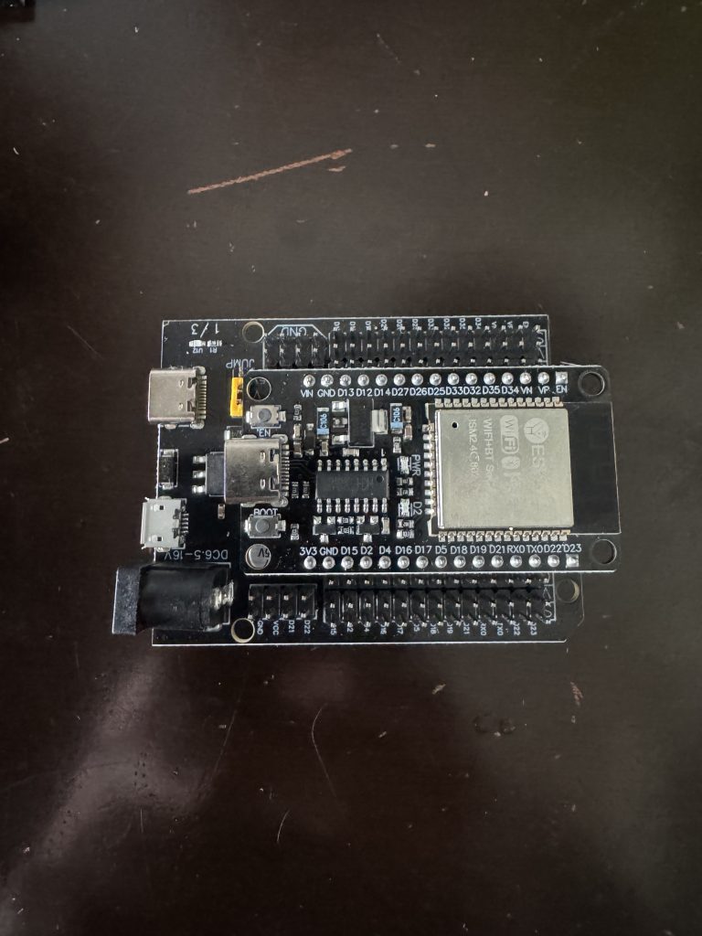
The ESP32 seated in its expansion shield. Line the D23 on the board up with the D23 on the shield and make sure the antenna end sits over the printed outline. It only goes in one way, but it will let you try the other way.
Wiring the anemometer to the ESP32
There are exactly two connections. The anemometer is a reed switch, so polarity does not matter.
- Snip the RJ11 plug off the anemometer lead. Strip the outer sheath. Inside there are only two conductors that matter (red and green on mine).
- Join each of those to a Dupont jumper wire.
- One jumper goes to the S pin of the D27 column on the shield. The other goes to the G pin of the same column. The middle V pin is never used. Do not put anything on V.
- Power the shield over USB-C from any phone charger.
That is the entire circuit. GPIO27 is set to input with the internal pull-up enabled in the config, so the pin sits high and every time the cups complete a revolution the reed switch pulls it to ground.
The bit I got wrong: the PCT-212 lever connectors. The anemometer’s internal wires are very thin, something like 26 to 28 AWG, and the levers simply do not grip them, even folded double. The connectors clamped down beautifully on the Dupont wire and left the anemometer wire loose inside, so I had a circuit that looked perfect and read nothing. I debugged it by halves: shorting the two Dupont tails together at the join made the count jump (so the board, the jumpers and GPIO27 were all fine), and touching the anemometer wires straight onto the tails while spinning the cups also worked. The levers were the only thing left. The fix was the oldest one there is: twist red to white, green to black, and tape it. It has been fine since.
The ESPHome config and flashing it
Install the ESPHome Device Builder from the Home Assistant add-on store (they are called “Apps” now, which I will keep calling add-ons until I die), create a new device, switch it to expert mode and paste this in. Put your WiFi SSID and password in the ESPHome secrets file.
esphome:
  name: bedroom-housing-wind
  friendly_name: Bedroom Housing Wind

esp32:
  board: esp32dev
  framework:
    type: esp-idf

logger:

api:
  encryption:
    key: !secret api_key

ota:
  - platform: esphome

wifi:
  ssid: !secret wifi_ssid
  password: !secret wifi_password
  # Fallback hotspot if it ever loses the house WiFi
  ap:
    ssid: "Housing-Wind Fallback"

captive_portal:

sensor:
  # One reed closure per cup rotation; 1 Hz is about 2.4 km/h in open air.
  # internal_filter soaks up reed-switch contact bounce.
  - platform: pulse_counter
    pin:
      number: GPIO27
      mode:
        input: true
        pullup: true
    # Software counting: the hardware PCNT caps its glitch filter at 13 us,
    # far too short to debounce a reed switch (milliseconds of bounce).
    use_pcnt: false
    name: "Cavity Wind Speed"
    id: cavity_wind
    unit_of_measurement: "km/h"
    icon: mdi:weather-windy
    accuracy_decimals: 1
    update_interval: 5s
    internal_filter: 10ms
    filters:
      # pulses/min -> Hz -> km/h (cavity units, see the text)
      - multiply: 0.04
      - sliding_window_moving_average:
          window_size: 3
          send_every: 1

  # Gust: the hottest 5 s sample of the last minute. Blowback is gusty
  # and the average hides it.
  - platform: copy
    source_id: cavity_wind
    name: "Cavity Wind Gust (1 min)"
    unit_of_measurement: "km/h"
    icon: mdi:weather-tornado
    accuracy_decimals: 1
    filters:
      - max:
          window_size: 12
          send_every: 12
          send_first_at: 12

  - platform: wifi_signal
    name: "WiFi Signal"
    update_interval: 120s
    entity_category: diagnostic

binary_sensor:
  - platform: status
    name: "Status"
Three things in there that are worth understanding rather than just pasting:
use_pcnt: false. The ESP32 has a hardware pulse counter and ESPHome uses it by default. Its glitch filter tops out at 13 microseconds. A reed switch bounces for milliseconds, so with the hardware counter every rotation registers as a handful of pulses and your wind speed is nonsense. Turning it off makes ESPHome count in software, whereinternal_filter: 10msactually works.multiply: 0.04. The pulse counter reports pulses per minute. Divide by 60 for Hz, multiply by 2.4 for the Misol’s spec of 2.4 km/h per Hz, and you get 0.04. Remember this is open-air calibration for cups that are not in open air.- The gust sensor. A copy of the speed sensor that keeps the maximum of the last twelve 5-second samples. The blowback that matters is gusty and a one-minute average of it looks tame. Every automation decision I make uses the gust, not the mean.
Flashing it
The first flash has to be over USB. After that everything is over the air. Things that cost me time, so they need not cost you any:
- The first USB cable I grabbed was charge-only. If the board powers up but nothing appears as a serial port, try another cable before you try anything else.
- I flashed from the HA Green’s own USB port. If you do the same and you also have a Zigbee dongle plugged in, do not pick /dev/ttyUSB0. That was my Zigbee stick. ESPHome will happily try to flash it.
- If the log shows
4-Way Handshake Timeoutover and over, your WiFi password is wrong. It is not a signal problem. Fix the secret and re-flash. - My IoT devices are on a separate VLAN. HA’s automatic discovery never saw the ESP32 across it, so I gave it a fixed IP on the router and added the ESPHome integration by IP address manually. Took thirty seconds once I stopped waiting for the discovery to fire.
The spin test
With the board plugged in indoors, I gave the cups a flick with a finger. The speed sensor went from 0 to 17.0 km/h and the gust sensor caught the 17.0 peak a minute later. The whole chain, cups to reed to GPIO to ESPHome to Home Assistant, was proven on the dining table before anything went near the housing.
I also tested it upside down, because the mounting plan was to hang the cups from above. Inverted, a flick reached 13.6 km/h with a long free coast, so the bearing does not care which way up it is, and since we are counting reed closures the direction of rotation is irrelevant too.
3D printing the mount (five goes at one peg)
The Misol anemometer is designed to push onto a plastic post that is part of a weather station mast. Underneath the cups there is a socket: a smooth 14 mm bore, 20 mm deep, with a 5 mm cross-hole for a locking screw 5 mm below the mouth. I did not have the mast, so I needed to print a peg that fits that socket and a bracket to hold the peg in the housing.
I do not have CAD skills. What I have is a Kobra 2 Pro, a roll of black PETG, and Claude, which wrote each part as a small Python script using the trimesh library from the measurements I gave it and spat out an STL. That turned out to be a surprisingly good way to iterate, because each new version was a one-number change to a script rather than an afternoon in Fusion.
Fit gauge 1: everything too skinny
Rather than guess the peg diameter, the first print was a fit gauge: a small plate with three pegs of 10.0, 10.5 and 11.0 mm. Every one of them rattled around in the socket. Way too much play. I had assumed the three internal fins I could see in the socket would grip a smaller peg. They do not.
Fit gauge 2: 13.8 mm is snug
Gauge 2 had five pegs of 12.0, 12.5, 13.0, 13.5 and 13.8 mm, each one taller than the last so I could tell them apart once printed. 13.8 was snug in the bore. Job done, I thought.
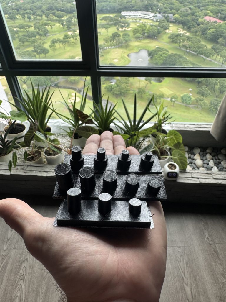
All three fit gauges. Front: gauge 1 (too skinny). Middle: gauge 2, which found the 13.8 mm bore. Back: gauge 3, which found the fin opening. Print settings 0.28 mm layers, 8% infill, no brim. Together they took less than an hour of printing and saved several bracket reprints.
Bracket v1 to v3: the fins are a depth stop, not a grip
Bracket v1 was a 44 mm round flange, 5 mm thick, with four countersunk screw holes and a 13.8 mm peg sticking 18.5 mm out of it, with a 3.4 mm cross-hole for the locking screw. It printed fine. It did not fit. The peg went in about 8 mm and stopped dead.
This is where measuring from the mouth of the socket rather than eyeballing it paid off. The three fins are not grippers at all. They are a depth stop 8.5 mm down, and the opening between them is only about 7 mm. My gauge 1 pegs had not been sliding past the fins and rattling. They had been resting on top of them, which is why all three felt equally loose. Gauge 2’s 13.8 mm peg was snug in the first 8 mm of bore and I had not pushed it any further.
v2 and v3 shortened the peg to sit on the fins, and v3 added a thin nose to poke between them. v3 was very nearly right and had one problem I only spotted holding it: the short peg left the locking screw’s channel open at the tip, so a hanging anemometer would push the screw straight out of the end. Not ideal for something bolted to the outside of a tower block.
Fit gauge 3: 7.5 mm nose
One more gauge, this time four columns each with the proven 13.8 x 8.2 mm seat and a nose of 6.5, 7.5, 8.5 or 9.5 mm on top. The 7.5 mm nose seated perfectly between the fins and they grip it. 8.5 would not go in.
Bracket v4: the one that works
v4 is a stepped peg: 44 mm flange, then a 13.8 mm seat 8.2 mm long that fills the bore and stops on the fins, then a 7.5 mm nose 9.5 mm long that goes through the fins to the bottom of the socket. The 3.4 mm cross-hole is at 7.5 mm below the flange, which puts it fully inside the seat, so the locking screw is enclosed on all sides and cannot walk out. A #6 self-tapper goes through the socket’s own hole and into it.
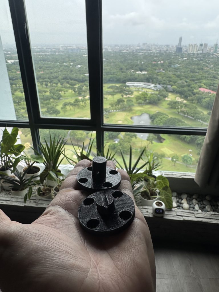
Two of the failures: bracket v1 (top, the long plain peg that stopped on the fins) and another attempt at the seat-plus-nose idea (bottom) that did not make the cut either. Both printed flange-down at 0.2 mm, 4 walls, 40% infill, with a brim.
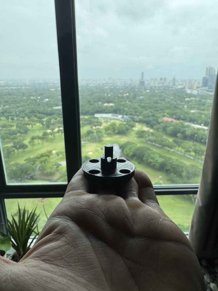
v4 close up. The cross-hole is inside the fat seat, not the thin nose, so the locking screw is captive.
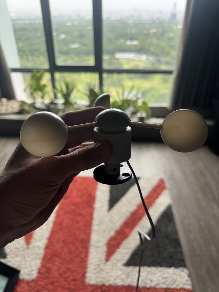
v4 seated in the anemometer’s socket. No wobble, and the locking screw hole lines up with the socket’s own.
The arm
The original plan was to screw the flange to the roof of the cavity and hang the cups from it. When I actually got the louvre open and looked, the roof was not usable, so the mount moved to the side panel of the cavity, at louvre height. That needed an arm: an 80 x 70 x 5 mm plate that screws to the panel with four #8 wood screws, a 24 x 20 mm beam with a 45 degree gusset, and a 44 mm round pad at the end, 115 mm out from the panel, with four 3.8 mm pilot holes on the same 34 mm circle as the flange. The v4 module screws up into the pad from below with four #6 self-tappers, and the anemometer hangs off it. There are two zip-tie slots through the beam for the cable.
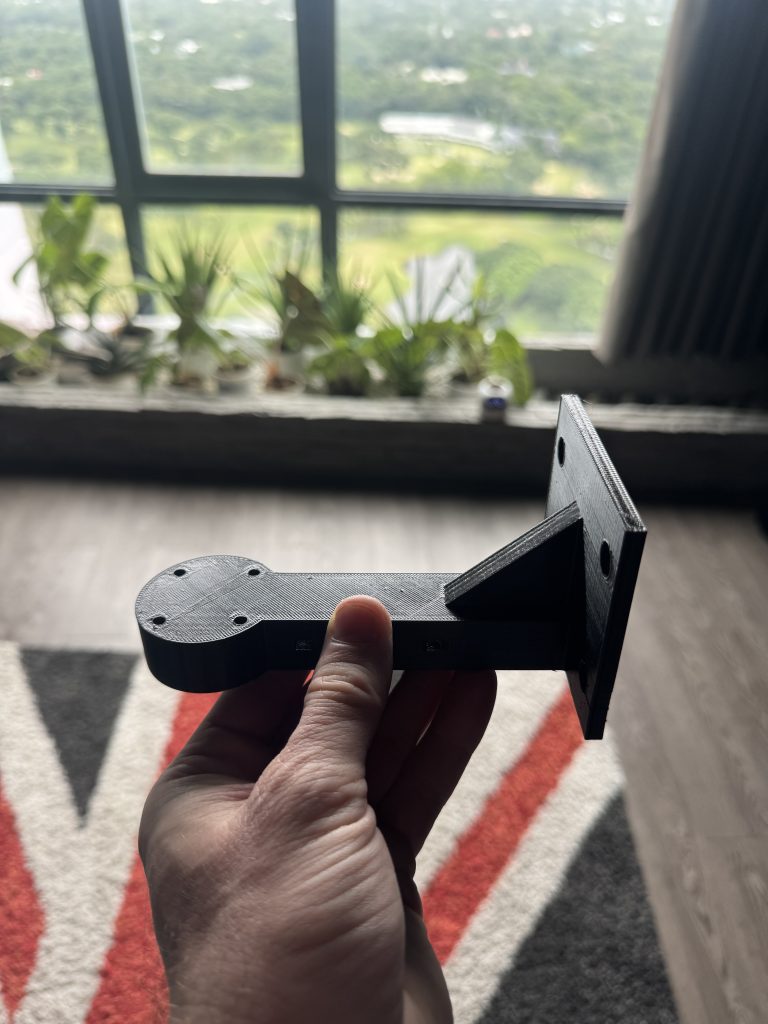
The arm, printed lying flat on its body so the plate and gusset need no support. Plate at the right, pad at the left.
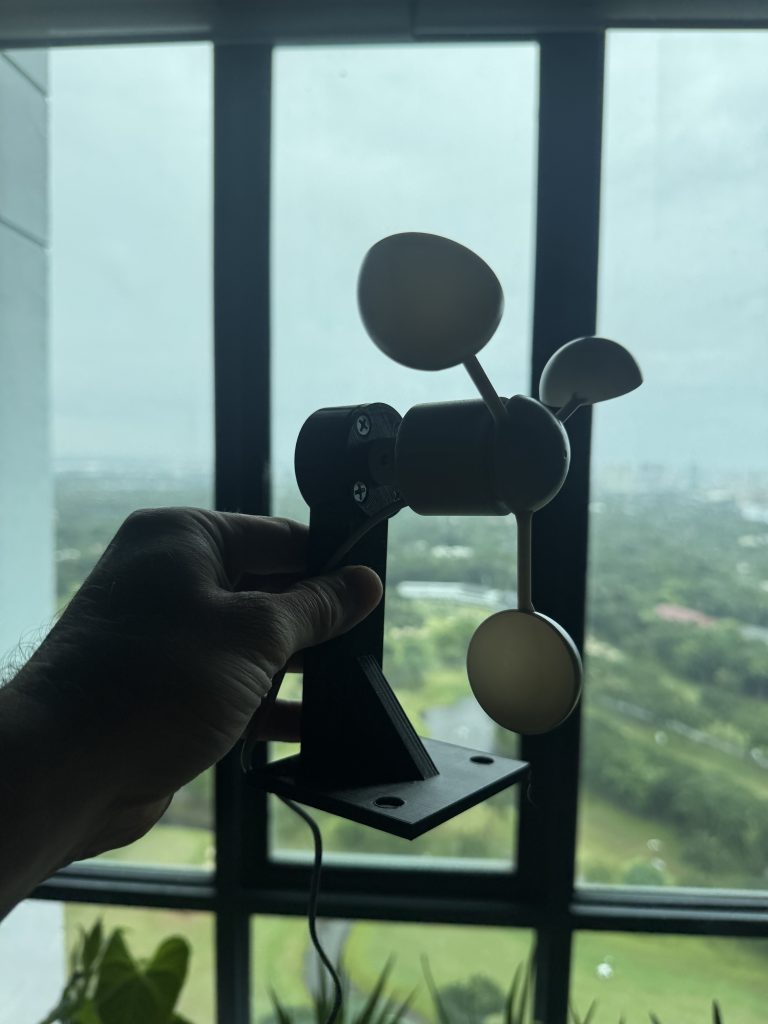
Assembled. Cups, v4 module, arm. The four self-tappers through the pad are visible on the flange.
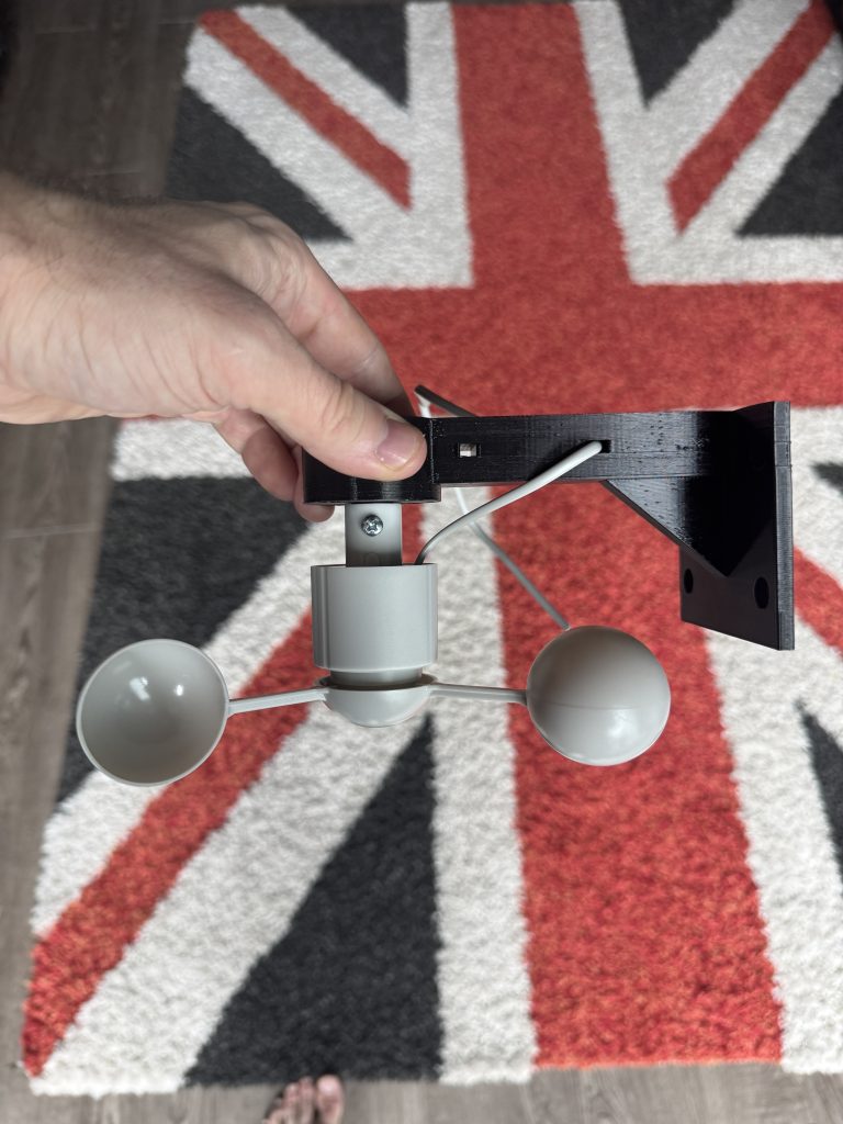
The way up it actually lives: plate against the side panel, cups hanging below the pad, lead zip-tied along the beam and off to the ESP32 indoors.
Download the STLs
These are the two final parts. You need one of each. If your anemometer is the same Misol WH-SP-WS01 the module will fit as-is. If your cavity is a different shape you will want to change the arm; the 115 mm reach and the 80 x 70 plate were sized for my side panel and my louvre height.
Print settings I used (Anycubic Kobra 2 Pro, black PETG, sliced in Anycubic Slicer Next):
- Module: flange down, 0.20 mm layers, 4 walls, 40% infill, brim.
- Arm: flat on its body as exported, 0.20 mm layers, 4 walls, 40% infill, brim. No supports needed.
- PETG rather than PLA on purpose. The cavity gets hot when the condenser is running and PLA would sag over a season.
Screws: 5 x #6 self-tapping pan head 3.5 x 16 mm (four for module to arm, one for the lock through the socket), 4 x #8 wood screw pan head 4.2 x 32 mm (arm to panel).
Mounting it in the housing
The rules I set myself, all of which are just common sense:
- Shaft vertical, cups clear of everything all the way round. Cup anemometers do not care which way the wind comes from but they do care about hitting the louvre.
- Cups behind the west louvre, because that is the wind I care about. The louvre also acts as a direction filter for free: strong cavity flow means west intrusion, which is exactly the condition that causes blowback.
- A drip loop in the cable before it passes through to the inside, and the pass-through sealed.
- Screws into the panel, not adhesive. Between the heat and the compressor vibration, tape would be on the pavement in a week.
- The ESP32 stays indoors on a phone charger. Only the cups and the lead are outside.
I temporarily mounted it on the 28th of August (that was the afternoon of the lever-connector debugging) and screwed it down properly the following evening. It has not moved since.
What it actually reads
Two things surprised me in the first 48 hours, one of them useful.
The cups sit in the condenser’s exhaust. The first evening the aircon started in dry mode at six minutes past eight and about ninety seconds later the cavity wind went from 3.5 to 23.5 km/h and stayed pinned there all night. With the aircon off, the same evening had read 0 to 6 with the airport reporting about 5 km/h and, in my expert opinion from the balcony, “little to no wind”. So while the condenser runs, the sensor reads a flat floor of roughly 23 to 24 cavity-km/h from the fan alone.
I briefly thought this ruined the whole thing. It does not. The fan floor is dead flat and utterly consistent, so real wind shows up as disturbance on top of it, and when the aircon is off you get the raw wind. As a bonus the anemometer is now also a condenser airflow health monitor. If that floor ever starts to droop, the louvre is clogged or the fan is dying, and I will know before the compressor does.
The louvre halves the wind. The first proper westerly with the aircon off, on the 1st of September, read a gusty 9 to 30 with a sustained figure of about 16 and a peak of 30.6 in the cavity, while the airport was reporting 31.5 km/h from the south-west. So the attenuation through the louvre is roughly half, and more importantly the gusty wobble of real wind looks nothing like the flat fan floor. That is the signature the automation keys on.
The Home Assistant side
ESPHome hands HA four entities: sensor.bedroom_housing_wind_cavity_wind_speed,
sensor.bedroom_housing_wind_cavity_wind_gust_1_min, a WiFi signal diagnostic and a status binary sensor that tells you the board is alive. Nothing else is required. The dashboard bit is a Mushroom header with the current speed, the gust and the airport reading, and a 12-hour history graph of all three so I can see the cavity against the airport at a glance.
The clever part is what I let the sensor do to the storm-protection automation, and just as importantly what I do not let it do.
The storm automation’s job is: when sustained west wind is hammering the housing, shut the bedroom aircon down before it thermal-protects itself, put the ceiling fan to maximum and switch the standing fan on. When it has been calm for long enough, stand down and put the room back to whatever scene is active. Before the anemometer, both the engage side and the stand-down side ran on forecast and airport data, and the stand-down was the bit that annoyed me: the forecast would hold at 39 km/h while the housing had gone quiet an hour ago and the aircon sat there off.
Now the anemometer owns the stand-down. If the cavity gust stays under a bar of 15 cavity-km/h for twenty minutes, the automation releases, whatever the forecast still claims. The bar came from the data: real blows read 18 to 30 plus, calm reads 0 to 7, and 15 splits the gap. It is an input_number so I can tune it from the dashboard without touching YAML. The trigger is just this:
      # Cups-calm: the housing's own anemometer says the blow is over,
      # whatever the forecast still claims. numeric_state only fires
      # while the value is a number, so "unavailable" can never release.
      - trigger: numeric_state
        entity_id: sensor.bedroom_housing_wind_cavity_wind_gust_1_min
        below: input_number.storm_cup_calm_gust
        for: "00:20:00"
        id: cups_calm
With two guards in the conditions: the ESP32’s status sensor must be on, and the airport must be reporting under 40 km/h. If the board has died, or the airport is reporting a genuine gale, a calm-looking cavity is not trusted and the old thirty-minute forecast-based calm path applies instead.
What the anemometer is not allowed to do is engage the protection, or veto it. Engage stays forecast-based. The reasoning is simple: a wiring fault, a chewed cable, or a stuck reed switch all read as 0.0 km/h, which looks exactly like a calm night. A sensor that can fail to “calm” must never be the thing that decides the aircon is safe to keep running. It only gets to say “the blow is over”, and only when the other evidence agrees it plausibly could be. Cheap sensors get read-only privileges until they have earned more, and mine has only had a month.
The airport corroboration is a small package that pulls the RPLL METAR every half hour and holds the last good value. It is there as a sanity ceiling and so the history graph has a reference line. It is not doing any control.
Final cost and verdict
| Item | PHP |
|---|---|
| Anemometer (AliExpress, delivered) | 1,001 |
| ESP32 + shield | 384 |
| Dupont wires | 56 |
| Lever connectors I did not end up using | 51 |
| About 60 g of PETG, nine screws | Negligible |
| Total | 1,492 |
For about twenty quid I have a live number for the one thing no weather service could tell me, the storm automation stands down when the wind actually stops rather than when a model thinks it might have, and I get a condenser health monitor thrown in. The only real difficulty in the whole build was one 14 mm socket with three fins in it, and now you have the STL you can skip that part entirely. Here it is doing its job in a bit of a blow:
The cups behind the west louvre in a westerly, 16th of September.
If you build one, the two things to remember are: measure the socket from the mouth, and do not trust lever connectors with thin wire. Everything else is copy and paste. If yours reads something daft, check the cable before you check the config, because the config has been running for a month and the cable is the bit outside in the rain.